This project is an offshoot of the Kinematic Navigation and Cartography Knapsack (KNaCK), a backpack-mounted LiDAR system that allows humans to map their environment. While KNaCK is being developed for astronaut situational awareness, integrating it onto an autonomous rover (KNaCK-Car) enables the system to asses an environment in advance before the arrival of astronauts and other vehicles.
KNaCK-Car is being developed concurrently with the Smart Video Guidance System (SVGS), a lightweight positioning system that only requires a LED target and smartphone-grade camera. SVGS provides reliable positioning, but has no way of detecting hazards. SVGS relies on KNaCK-Car to provide a hazard map, eliminating the need for power-hungry LiDAR scanners on all but the initial scouting vehicle.
This project uses the Lunar Terrain Field (LTF) at Marshall Space Flight Center to provide an accurate testing environment (shown in Figure 1.1).
Figures 1.2 and 1.3 show two maps created by KNaCK-Car. The original KNaCK is focused entirely on 3D mapping; this can be directly ported to KNaCK-Car. The development of KNaCK-Car is thus focused on 2D mapping, which creates the hazard map for subsequent vehicles.
The navigation of KNaCK-Car is built upon Robot Operating System (ROS) and its Navigation 2 (Nav2) framework. Nav2 provides accessible means of simultaneous localization and mapping (SLAM), but is mainly intended for structured environments such as warehouses. Thus, most of KNaCK-Car's technical challenges involve adapting this 2D SLAM software to function in an environment with uneven terrain and non-uniform obstacles.
Figure 1.4 shows KNaCK-Car navigating through a series of hallways. One can clearly see "scan matching" taking place, wherein the robot matches its LiDAR scan to the map like a puzzle piece. This ensures accurate positioning in the face of sensor errors.
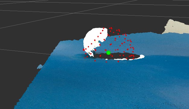
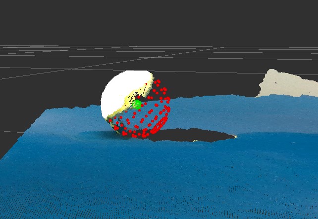
Figure 1.5 shows similar scan matching in the LTF. This was a vast improvement over an earlier test (shown in Figure 1.3), which failed to detect several hazards in the "hallway" between two berms.
At the start of my internship, KNaCK-Car's hardware was all in place but there was no software implementation beyond manual driving with a remote control. Over the course of my internship, I delivered:
- Software drivers for our LiDAR scanner, built to interface with ROS.
- ROS system architecture between sensors, rover drivetrain, and navigation programs.
- Configuration of Nav2 for KNaCK-Car.
-
C++ and Python programs that process 3D environmental data into 2D.
- I.E. Prevent traversable slopes from registering as hazards.
- Rigorous documentation and operating procedures, ensuring development can continue after my internship ends.
- Debugging and general technical support for KNaCK and SVGS.
At my internship's closeout, KNaCK-Car is capable of SLAM both in structured environments and the Lunar Terrain Field. KNaCK-Car can autonomously navigate between user-defined waypoints, pathfinding around obstacles and updating its path as the map evolves. SVGS demonstrated usage of a hazard map generated by KNaCK-Car, fulfilling KNaCK-Car's role in the mission architecture.